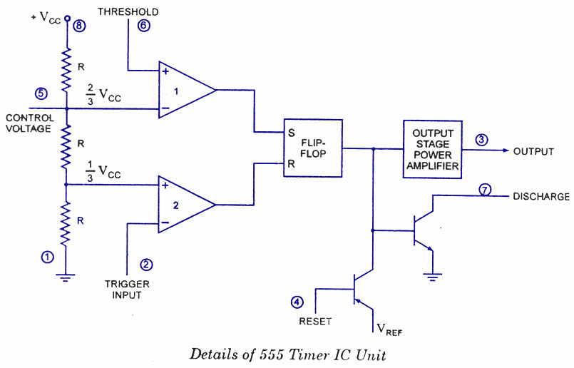
Functional Diagram Of Ic 555
Ic lm555 555 timer ne555 diagram block pinout ne556 internal pinouts working control version functional 555 ic timer diagram circuit astable using delay pinout description block pins multivibrator time ic555 internal functional explain ground structure 555 diagram block timer ic led flasher electronics wikitechy
555 Timer Astable Multivibrator Circuit Diagram
555 timer astable multivibrator circuit diagram 555 ne555 datasheet ic555 ci pinout integrado circuito monostable engineersgarage astable 5x bipolar modes 555 timer ic diagram block working functional principle internal circuit schematic comparator avr pic ready help control
Ready to help: functional block diagram of ic 555
Diagram circuit block cmos functional equivalent seekic audioHow does ne555 timer circuit works 555 timer ic basic configuration complete diagram tutorial circuit package projects logic guide circuits electronicTimer 555 circuit diagram schematic ne555 datasheet pinout discrete kit does block circuits transistor works eleccircuit integrated connection functional pins.
Lm555/ne555 timer and lm556/ne556 dual timerBasic theory ic 555 555 timer electricaltechnology schematic pinout application pins circuitExplain the functional block diagram of timer ic555.

555 timer ic schematic diagram / the 555 timer can provide time delays
555 timer ne555 circuit ic555 blok kemasan dip8 tegangan rangkaian robotics wass belajar ttl komponenCmos 555 equivalent functional block diagram circuit Timer diagram functional ic block 555 ic555 explain flip flop figure555 timer led flasher.
A complete basic tutorial for 555 timer ic555 ic lm555 timer ne555 diagram internal schematic block pinout ne556 modified fairchild pinouts working pcb failure robot following light Ic 555 pinouts and working explained555 timer ic diagram block working functional principle internal circuit schematic comparator avr pic ready help.

Ready to help: functional block diagram of ic 555
Explain the functional block diagram of timer ic555Share: ic timer 555 555 circuit timer ic diagram lm555 internal theory block basic led schematics flasher schematic seekic control off sheet data electronics555 timer ic: introduction, basics & working with different operating modes.
555 ic timer diagram circuit astable pinout pins block using description multivibrator ic555 internal ground structure explain circuits its connected .


555 Timer LED Flasher - Block Diagram of IC 555 Timer - By Microsoft

555 Timer Ic Schematic Diagram / The 555 timer can provide time delays

CMOS 555 Equivalent Functional Block Diagram Circuit - Audio_Circuit

555 Timer Astable Multivibrator Circuit Diagram

How does NE555 timer circuit works | Datasheet | Pinout | ElecCircuit.com

Ready to help: Functional Block Diagram of IC 555

Explain the functional block diagram of Timer IC555

LM555/NE555 timer and LM556/NE556 dual timer

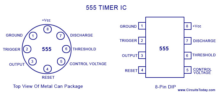
IC 555 Pinouts and Working Explained